Making a Multiplayer FPS in C++ Part 7: The Vulkan Projection Matrix, and Other Graphics Things
In the previous part of the series I mostly did some miscellaneous cleanup. This part unfortunately has no netcode whatsoever - it’s all about graphics (browse code here, it’s not pretty).
“You’re Not A Graphics Programmer, Stupid”
I’m no graphics guy, but I’m hoping I can still make an acceptable renderer. I’m trying to take a from-scratch approach with this thing, and graphics will be no exception. This means I need to derive the most basic building blocks like projection and transformation matrices, armed only with my B grade in A-Level maths from more than a decade ago. Though you don’t ever really need to do this sort of thing these days, it’s still (in my view) an interesting and worthwhile exercise.
The Coordinate System
Firstly I need to pick a coordinate system. For some reason, I always liked positive X-axis right, positive Y-axis up, and positive Z-axis forwards. I really have no idea why, but I found this tweet which nicely sums up the different coordinate systems and which engines/programs use which:
Here, have a coordinate system chart! pic.twitter.com/riYtt6tLEd
— Freya the stray (@FreyaHolmer) September 18, 2015
It seems that I’m weird in thinking that Y is up (maybe it’s because in graphics, Y is up/down the screen). It also seems that Unreal are on their own with left-handed Z-up, right-handed Z-up has Cryengine(and Lumberyard?), Source Engine, and more importantly Max and Blender. Seeing as I’m a sheep, I’ll just follow those guys - right-handed Z-up. That means positive X-axis right, positive Y-axis forward, and positive Z-axis up.
Calculating the Projection Matrix
To render in 3D at all, we need to project from 3D points in space, to 2D points on the screen. This projection process ultimately ends with Normalised Device Coordinates (NDC), with Vulkan the top-left corner of the window is (-1, -1) in X and Y, and the bottom-right corner of the window is (1, 1). Regardless of the aspect ratio of the screen, it’s always in that range from edge to edge. The Z component is depth, and that should be in the range of 0 to 1, from closest to furthest respectively.
The graphics API doesn’t actually want NDC coordinates to do its drawing business though, it wants Clip Coordinates, which are converted to NDC coordinates by dividing by the W component (this is the Perspective Division).
$$ NDC = {{(Clip_X, \text{ } Clip_Y, \text{ } Clip_Z)} \over Clip_W} $$
So you could also say that:
$$ Clip = (NDC_X * Clip_W, \text{ } NDC_Y * Clip_W, \text{ } NDC_Z * Clip_W, \text{ } Clip_W) $$
In summary, the projection matrix needs to carry out the following transformation:
$$(World_X, \text{ } World_Y, \text{ } World_Z) \rightarrow (NDC_X * Clip_W, \text{ } NDC_Y * Clip_W, \text{ } NDC_Z * Clip_W, \text{ } Clip_W) $$
So, a “camera” has a few key properties:
- field of view (FOV) - this can be either horizontal or vertical
- aspect ratio - width/height of the screen, this can be used to calculate the field of view in the other direction
- near clipping plane - the distance away from the camera origin that the screen sits, in world-space
- far clipping plane - points further from the camera origin than this will not be drawn
These properties define the camera frustum, 3D points outside of this volume will be ignored:
Note: I like camera FOV to be vertical, and then calculate the horizontal. Let’s say someone has a really wide monitor, if FOV is fixed horizontally, then effectively for them the vertical FOV is reduced like they’re looking through a letterbox. I prefer to have a fixed sensible vertical FOV, and then let horizontal FOV scale based on the aspect ratio of the screen.
Imagine we’re projecting the z component of the point:
It will be projected along this line towards the camera.

Passing through the near plane, this is where the projected point will be on the screen.
Finding the position on the near plane is a case of solving two triangles. The first triangle is from the camera to the point:
Trig 101 - the 3 sides of a right-angled triangle are referred to as opposite (the side opposite angle θ), adjacent (the other side which forms the right-angle of the triangle), and hypotenuse (the longest side, opposite the right-angle).
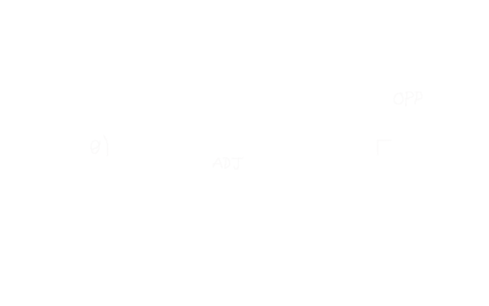
The Z coordinate is the opposite side, and the Y coordinate is the adjacent side.
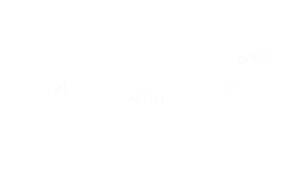
So θ can be calculated (using SOHCAHTOA) like this:
$$ \tan(\theta) = {opp \over adj} $$ $$ \theta = \arctan({opp \over adj}) $$ $$ \theta = \arctan({World_Z \over World_Y}) $$
The second triangle is from the camera to the projected point:
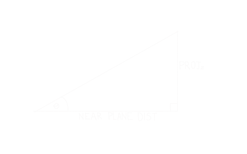
θ will be the same as in the first triangle, the near plane distance is the adjacent side, and the opposite side is the projected Z coordinate of the point on the near plane. Armed with θ and the near plane distance, the projected Z is calculated like this:
$$ \tan(\theta) = {opp \over adj} $$ $$ \tan(\theta) * adj = opp $$ $$ \tan(\theta) * \text{near}\text{\textunderscore}\text{plane}\text{\textunderscore}\text{distance} = Proj_Z $$
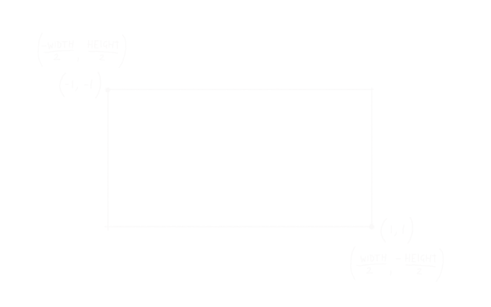
This gives the projected coordinate in world-space, but remember we need NDC coordinates in the range of -1 to +1. The near plane in world space ranges from (-width/2, height/2) to (width/2, -height/2), so we need to map these world space positions to the NDC coordinates (-1, -1) and (1, 1) respectively.
In order to calculate this we need to know the height of the near plane in world-space. How do we find that out? More triangles!
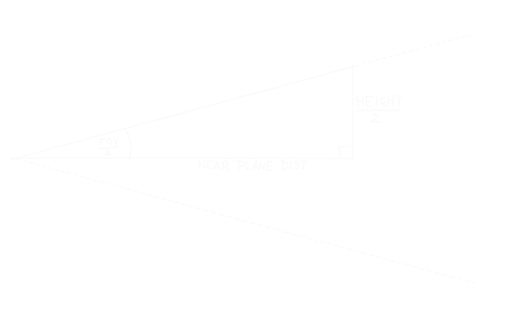
This triangle is made up of a half of the camera field-of-view, so the opposite side of the triangle will be half the size of the near plane in world-space. Calculate just like projecting the point earlier:
$$ \tan(\theta) = {opp \over adj} $$ $$ \tan(\theta) * adj = opp $$ $$ \tan({fov \over 2}) * \text{near}\text{\textunderscore}\text{plane}\text{\textunderscore}\text{distance} = {\text{near}\text{\textunderscore}\text{plane}\text{\textunderscore}\text{height} \over 2} $$
The near plane will span world Z coordinates from -height/2 to +height/2, and these will map to +1 to -1 in NDC (remember +ve Y NDC coordinates go down the screen, whereas +ve Z world coordinates go up the screen). So to convert from a world-space projected Z value to NDC Y, just divide by negative half the size:
$$ NDC_Y = {Proj_Z \over -({\text{near}\text{\textunderscore}\text{plane}\text{\textunderscore}\text{height} \over 2})} $$
Putting the whole thing together:
$$ NDC_Y = {Proj_Z \over -({\text{near}\text{\textunderscore}\text{plane}\text{\textunderscore}\text{height} \over 2})} $$
$$ NDC_Y = {\tan(\theta) * \text{near}\text{\textunderscore}\text{plane}\text{\textunderscore}\text{distance} \over -({\text{near}\text{\textunderscore}\text{plane}\text{\textunderscore}\text{height} \over 2})} $$
$$ NDC_Y = {\tan(\arctan({World_Z \over World_Y})) * \text{near}\text{\textunderscore}\text{plane}\text{\textunderscore}\text{distance} \over -({\text{near}\text{\textunderscore}\text{plane}\text{\textunderscore}\text{height} \over 2})} $$
$$ NDC_Y = {(\tan(\arctan({World_Z \over World_Y})) * \text{near}\text{\textunderscore}\text{plane}\text{\textunderscore}\text{distance}) \over -(\tan({fov \over 2} ) * \text{near}\text{\textunderscore}\text{plane}\text{\textunderscore}\text{distance}) } $$
$$ NDC_Y = {\htmlStyle{text-decoration: line-through;}{(\tan(\arctan(}{World_Z \over World_Y})) \htmlStyle{text-decoration: line-through;}{* \text{near}\text{\textunderscore}\text{plane}\text{\textunderscore}\text{distance}}) \over -(\tan({fov \over 2} ) \htmlStyle{text-decoration: line-through;}{* \text{near}\text{\textunderscore}\text{plane}\text{\textunderscore}\text{distance}}) } $$
$$ NDC_Y = {{World_Z \over World_Y} \over -\tan({fov \over 2} ) } $$
There’s a problem with this - the part where Z is divided by Y, matrix multiplication doesn’t allow us to divide one component of the input by another component. This isn’t an actual problem though, remember the value we’re actually trying to get out from the matrix multiplication is the clip coordinates, the magical graphics fairies will divide the clip coordinates with the W component of the clip coordinates. So we can just use the world Y value:
$$ Clip_W = World_Y $$ $$ Clip_Y = NDC_Y * Clip_W $$ $$ Clip_Y = NDC_Y * World_Y $$ $$ Clip_Y = {{World_Z \over World_Y} \over -\tan({fov \over 2} ) } * World_Y $$ $$ Clip_Y = {{World_Z \over \htmlStyle{text-decoration: line-through;}{World_Y}} \over -\tan({fov \over 2} ) } \htmlStyle{text-decoration: line-through;}{* World_Y} $$ $$ Clip_Y = {World_Z \over -\tan({fov \over 2} ) } $$
Next to work on the X component, the formula is the same as before, except we divide by +tan(fov/2), because NDC coordinates in the X-axis go positive from left to right, just like the world coordinates:
$$ Clip_X = {World_X \over \tan({fov \over 2})} $$
But the X component will be using a different FOV (horizontal, rather than vertical). As I said earlier, we calculate this from the vertical FOV and the camera aspect ratio. Remember though, we use the FOV to calculate the world-space size of the near plane, so we don’t actually need to know the horizontal FOV, just the horizontal size of the near plane. The aspect ratio of the near plane will be the same as the aspect ratio of the camera, so we can find the horizontal size of the near plane by multiplying the vertical size by aspect ratio:
$$ Clip_X = {World_X \over \tan({fov \over 2}) * \text{aspect}\text{\textunderscore}\text{ratio}} $$
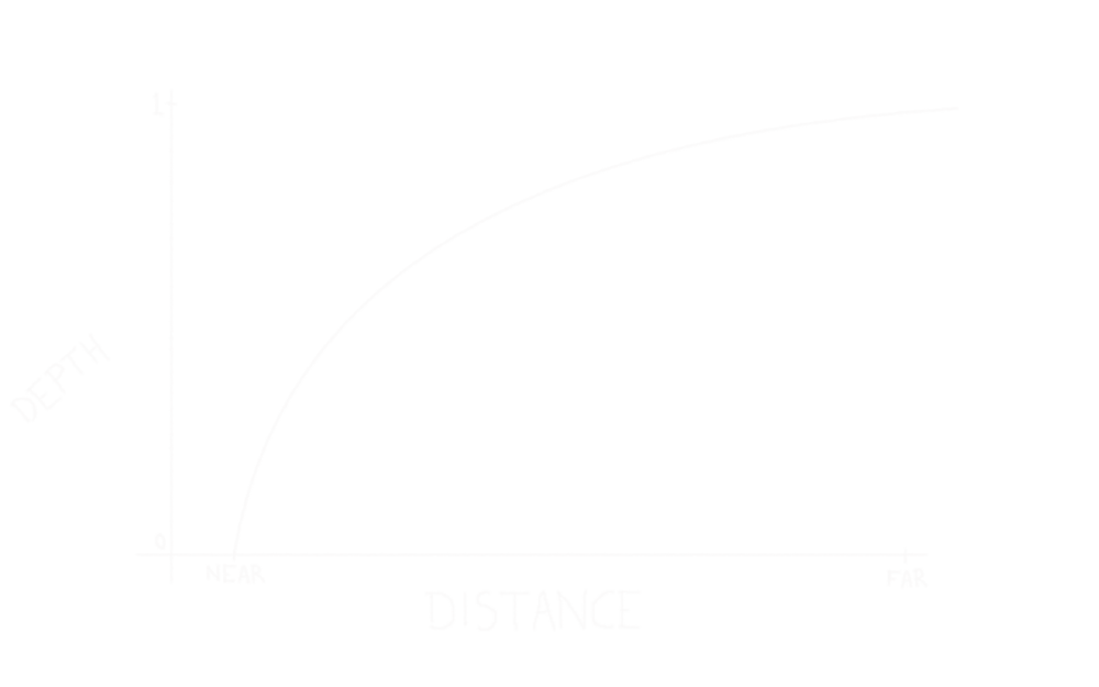
Unlike X and Y, Z (depth) should range from 0 to 1, with 0 being close to the camera, and 1 being far away. Therefore 0 will map to the near plane, and 1 will map to the far plane. That could be done with a simple linear relationship, but it’s better to actually give more space in the depth buffer to objects which are closer to the camera. This is because you’re more likely to notice depth related artifacts like Z-fighting on things which are in the foreground rather than the background. A good formula to base this off is:
$$ NDC_Z = {m \over World_Y} + c $$
We also know that this formula will be equal to 0 when the Y value is equal to the near plane:
$$ NDC_Z = {m \over World_Y} + c $$ $$ 0 = {m \over near} + c $$ $$ c = -{m \over near} $$
And a Y value equal to the far plane will produce a value of 1:
$$ 1 = {m \over far} + c $$ $$ c = 1 - {m \over far} $$
These two simultaneous equations allow to solve for m:
$$ c = -{m \over near} $$ $$ c = 1 - {m \over far} $$ $$ -{m \over near} = 1 - {m \over far} $$ $$ -m = near - {m * near \over far} $$ $$ -m * far = (near * far) - (m * near) $$ $$ (m * near) - (m * far) = near * far $$ $$ m * (near - far) = near * far $$ $$ m = {near * far \over near - far} $$
Use the value of m to solve for c:
$$ 0 = {m \over near} + c $$ $$ 0 = {{near * far \over near - far} \over near} + c $$ $$ 0 = {far \over near - far} + c $$ $$ c = {-far \over near - far} $$ $$ c = {far \over far - near} $$
Putting it all together:
$$ NDC_Z = {{near * far \over near - far} \over World_Y} + {far \over far - near} $$
However, again the value that is output from the matrix will have this division by the world Y component done automatically, so just multiply that formula by Y to get the desired output:
$$ Clip_Z = {near * far \over near-far} + {World_Y * far \over far-near} $$
Now to combine all of these into a 4x4 projection matrix. Matrices are multiplied along the rows of the projection matrix, and down the column of the vector being transformed (more on matrix multiplication here if needed).
$$ \begin{bmatrix} Out_X \\ Out_Y \\ Out_Z \\ Out_W \end{bmatrix} = \begin{bmatrix} \color{IndianRed}{M_{11}} & \color{PaleGreen}{M_{12}} & \color{LightSkyBlue}{M_{13}} & \color{Khaki}{M_{14}} \\ \color{IndianRed}{M_{21}} & \color{PaleGreen}{M_{22}} & \color{LightSkyBlue}{M_{23}} & \color{Khaki}{M_{24}} \\ \color{IndianRed}{M_{31}} & \color{PaleGreen}{M_{32}} & \color{LightSkyBlue}{M_{33}} & \color{Khaki}{M_{34}} \\ \color{IndianRed}{M_{41}} & \color{PaleGreen}{M_{42}} & \color{LightSkyBlue}{M_{43}} & \color{Khaki}{M_{44}} \end{bmatrix} \begin{bmatrix} \color{IndianRed}{In_X} \\ \color{PaleGreen}{In_Y} \\ \color{LightSkyBlue}{In_Z} \\ \color{Khaki}{In_W} \end{bmatrix} $$
So if we start with the first row of the matrix, which will produce the output X value:
$$ Out_X = (\color{IndianRed}{M_{11} * In_X}) + (\color{PaleGreen}{M_{12} * In_Y}) + (\color{LightSkyBlue}{M_{13} * In_Z}) + (\color{Khaki}{M_{14} * In_W}) $$
The desired output value is:
$$ \color{IndianRed}{In_X} \over {\tan({fov \over 2}) * \text{aspect}\text{\textunderscore}\text{ratio}} $$
The only input component needed is X, so that will just be the M11 value, making the first row of the matrix:
$$\begin{bmatrix} \color{IndianRed}{1 \over \tan({fov \over 2}) * \text{aspect}\text{\textunderscore}\text{ratio}} & \color{PaleGreen}{0} & \color{LightSkyBlue}{0} & \color{Khaki}{0} \end{bmatrix}$$
Then for the second row:
$$ Out_Y = (\color{IndianRed}{M_{21} * In_X}) + (\color{PaleGreen}{M_{22} * In_Y}) + (\color{LightSkyBlue}{M_{23} * In_Z}) + (\color{Khaki}{M_{24} * In_W}) $$
The desired output of which is:
$$ \color{LightSkyBlue}{In_Z} \over {-\tan({fov \over 2})} $$
Which will be M23 value, making the second row:
$$ \begin{bmatrix} \color{IndianRed}{0} & \color{PaleGreen}{0} & \color{LightSkyBlue}{-1 \over \tan({fov \over 2})} & \color{Khaki}{0} \end{bmatrix} $$
The third row will output the Z (depth) value:
$$ Out_Z = (\color{IndianRed}{M_{31} * In_X}) + (\color{PaleGreen}{M_{32} * In_Y}) + (\color{LightSkyBlue}{M_{33} * In_Z}) + (\color{Khaki}{M_{34} * In_W}) $$
Which needs to output:
$$ \color{Khaki}{near * far \over near - far} + \color{PaleGreen}{In_Y * far \over far - near} $$
This makes use of two components, the Y component is the obvious one (M32), and a constant. For the constant the W component (M34) is used (the input vertex will have 1 for the W component):
$$\begin{bmatrix} \color{IndianRed}{0} & \color{PaleGreen}{far \over far - near} & \color{LightSkyBlue}{0} & \color{Khaki}{near * far \over near - far} \end{bmatrix}$$
The final row will output the W value used to divide the X/Y/Z values to output NDC coordinates, and will be the distance from the camera to the point. So all that’s needed is the Y component, which means the final row will be:
$$\begin{bmatrix} \color{IndianRed}{0} & \color{PaleGreen}{1} & \color{LightSkyBlue}{0} & \color{Khaki}{0} \end{bmatrix}$$
All of those rows together:
$$\begin{bmatrix} \color{IndianRed}{1 \over \tan({fov \over 2}) * \text{aspect}\text{\textunderscore}\text{ratio}} & \color{PaleGreen}{0} & \color{LightSkyBlue}{0} & \color{Khaki}{0} \\ \color{IndianRed}{0} & \color{PaleGreen}{0} & \color{LightSkyBlue}{-1 \over \tan({fov \over 2})} & \color{Khaki}{0} \\ \color{IndianRed}{0} & \color{PaleGreen}{far \over far - near} & \color{LightSkyBlue}{0} & \color{Khaki}{near * far \over near - far} \\ \color{IndianRed}{0} & \color{PaleGreen}{1} & \color{LightSkyBlue}{0} & \color{Khaki}{0} \end{bmatrix}$$
Calculating The Model Matrix
The next matrix that’ll be needed is a model matrix - again you can just look this up, but figuring it out from first principles is quite simple. To recap, transforming a vector with a matrix:
$$ Out_X = (\color{IndianRed}{M_{11} * In_X}) + (\color{PaleGreen}{M_{12} * In_Y}) + (\color{LightSkyBlue}{M_{13} * In_Z}) + (\color{Khaki}{M_{14} * In_W}) $$ $$ Out_Y = (\color{IndianRed}{M_{21} * In_X}) + (\color{PaleGreen}{M_{22} * In_Y}) + (\color{LightSkyBlue}{M_{23} * In_Z}) + (\color{Khaki}{M_{24} * In_W}) $$ $$ Out_Z = (\color{IndianRed}{M_{31} * In_X}) + (\color{PaleGreen}{M_{32} * In_Y}) + (\color{LightSkyBlue}{M_{33} * In_Z}) + (\color{Khaki}{M_{34} * In_W}) $$ $$ Out_W = (\color{IndianRed}{M_{41} * In_X}) + (\color{PaleGreen}{M_{42} * In_Y}) + (\color{LightSkyBlue}{M_{43} * In_Z}) + (\color{Khaki}{M_{44} * In_W}) $$
When transforming a vector which is just a direction (e.g. a surface normal), the W component will always be 0, so we can simplify the above to:
$$ Out_X = (\color{IndianRed}{M_{11} * In_X}) + (\color{PaleGreen}{M_{12} * In_Y}) + (\color{LightSkyBlue}{M_{13} * In_Z}) $$ $$ Out_Y = (\color{IndianRed}{M_{21} * In_X}) + (\color{PaleGreen}{M_{22} * In_Y}) + (\color{LightSkyBlue}{M_{23} * In_Z}) $$ $$ Out_Z = (\color{IndianRed}{M_{31} * In_X}) + (\color{PaleGreen}{M_{32} * In_Y}) + (\color{LightSkyBlue}{M_{33} * In_Z}) $$ $$ Out_W = (\color{IndianRed}{M_{41} * In_X}) + (\color{PaleGreen}{M_{42} * In_Y}) + (\color{LightSkyBlue}{M_{43} * In_Z}) $$
Whereas if the vector is a point in space, then W will always be 1:
$$ Out_X = (\color{IndianRed}{M_{11} * In_X}) + (\color{PaleGreen}{M_{12} * In_Y}) + (\color{LightSkyBlue}{M_{13} * In_Z}) + \color{Khaki}{M_{14}} $$ $$ Out_Y = (\color{IndianRed}{M_{21} * In_X}) + (\color{PaleGreen}{M_{22} * In_Y}) + (\color{LightSkyBlue}{M_{23} * In_Z}) + \color{Khaki}{M_{24}} $$ $$ Out_Z = (\color{IndianRed}{M_{31} * In_X}) + (\color{PaleGreen}{M_{32} * In_Y}) + (\color{LightSkyBlue}{M_{33} * In_Z}) + \color{Khaki}{M_{34}} $$ $$ Out_W = (\color{IndianRed}{M_{41} * In_X}) + (\color{PaleGreen}{M_{42} * In_Y}) + (\color{LightSkyBlue}{M_{43} * In_Z}) + \color{Khaki}{M_{44}} $$
Translation is the simplest part, this is just an addition. We can see above that M14 will be added to X, M24 to Y, and M34 to Z. So the translation vector can be stored in those three components of the matrix. We’ll want to maintain the existing X/Y/Z/W components too, just like the identity matrix, so M11/M22/M33/M44 will all be 1.
$$\begin{bmatrix} \color{IndianRed}{1} & \color{PaleGreen}{0} & \color{LightSkyBlue}{0} & \color{Khaki}{Translation_X} \\ \color{IndianRed}{0} & \color{PaleGreen}{1} & \color{LightSkyBlue}{0} & \color{Khaki}{Translation_Y} \\ \color{IndianRed}{0} & \color{PaleGreen}{0} & \color{LightSkyBlue}{1} & \color{Khaki}{Translation_Z} \\ \color{IndianRed}{0} & \color{PaleGreen}{0} & \color{LightSkyBlue}{0} & \color{Khaki}{1} \end{bmatrix}$$
Next is rotation. The convention is that a rotation of θ radians around an axis, is counter-clockwise around that axis, if that axis is pointing towards the observer:
Rotating a point around the origin is just a case of using a combination of sin(θ) and cos(θ) to move the point in an arc. I don’t find this stuff intuitive, so I just brute-forced a solution.
So let’s start with a rotation around the X-axis. Take for example, the point (Y=0, Z=2), we don’t care about X here because we’re rotating around the X-axis:
We can see that a rotation of 90° produces (Y=-2, Z=0). We also know that cos(90°)=0, and sin(90°)=1. Therefore in this case, we could say:
$$ Out_Y = \color{LightSkyBlue}{-\sin(\theta) * In_Z} $$
Looking at a rotation of 180°, we get (Y=0, Z=-2). Cos(180°)=-1, sin(180°)=0, so:
$$ Out_Z = \color{LightSkyBlue}{\cos(\theta) * In_Z} $$
Now do the same process with the point (Y=2, Z=0):
A rotation of 90° results in (Y=0, Z=2), cos(90°)=0, and sin(90°)=1, so:
$$ Out_Z = \color{PaleGreen}{\sin(\theta) * In_Y} $$
A rotation of 180° results in (Y=-2, Z=0), cos(180°)=-1, sin(180°)=0, so:
$$ Out_Y = \color{PaleGreen}{\cos(\theta) * In_Y} $$
Putting it all together:
$$ Out_Y = (\color{PaleGreen}{\cos(\theta) * In_Y}) - (\color{LightSkyBlue}{\sin(\theta) * In_Z}) $$ $$ Out_Z = (\color{PaleGreen}{\sin(\theta) * In_Y}) + (\color{LightSkyBlue}{\cos(\theta) * In_Z}) $$
Going all the way back to the output of the matrix:
$$ Out_Y = (\color{IndianRed}{M_{21} * In_X}) + (\color{PaleGreen}{M_{22} * In_Y}) + (\color{LightSkyBlue}{M_{23} * In_Z}) + \color{Khaki}{M_{24}} $$ $$ Out_Z = (\color{IndianRed}{M_{31} * In_X}) + (\color{PaleGreen}{M_{32} * In_Y}) + (\color{LightSkyBlue}{M_{33} * In_Z}) + \color{Khaki}{M_{34}} $$
So we can see that:
$$ \color{PaleGreen}{M_{22}} = \cos(\theta) $$ $$ \color{LightSkyBlue}{M_{23}} = -\sin(\theta) $$ $$ \color{PaleGreen}{M_{32}} = \sin(\theta) $$ $$ \color{LightSkyBlue}{M_{33}} = \cos(\theta) $$
So the matrix to rotate around the X-axis should look like this:
$$\begin{bmatrix} \color{IndianRed}{1} & \color{PaleGreen}{0} & \color{LightSkyBlue}{0} & \color{Khaki}{0} \\ \color{IndianRed}{0} & \color{PaleGreen}{\cos(\theta)} & \color{LightSkyBlue}{-\sin(\theta)} & \color{Khaki}{0} \\ \color{IndianRed}{0} & \color{PaleGreen}{\sin(\theta)} & \color{LightSkyBlue}{\cos(\theta)} & \color{Khaki}{0} \\ \color{IndianRed}{0} & \color{PaleGreen}{0} & \color{LightSkyBlue}{0} & \color{Khaki}{1} \end{bmatrix}$$
Repeat the process for rotations around Y and Z - I won’t bore you with the working for those, but the matrix to rotate around the Y-axis looks like this:
$$\begin{bmatrix} \color{IndianRed}{\cos(\theta)} & \color{PaleGreen}{0} & \color{LightSkyBlue}{\sin(\theta)} & \color{Khaki}{0} \\ \color{IndianRed}{0} & \color{PaleGreen}{1} & \color{LightSkyBlue}{0} & \color{Khaki}{0} \\ \color{IndianRed}{-\sin(\theta)} & \color{PaleGreen}{0} & \color{LightSkyBlue}{\cos(\theta)} & \color{Khaki}{0} \\ \color{IndianRed}{0} & \color{PaleGreen}{0} & \color{LightSkyBlue}{0} & \color{Khaki}{1} \end{bmatrix}$$
The matrix to rotate around the Z-axis looks like this:
$$\begin{bmatrix} \color{IndianRed}{\cos(\theta)} & \color{PaleGreen}{-\sin(\theta)} & \color{LightSkyBlue}{0} & \color{Khaki}{0} \\ \color{IndianRed}{\sin(\theta)} & \color{PaleGreen}{\cos(\theta)} & \color{LightSkyBlue}{0} & \color{Khaki}{0} \\ \color{IndianRed}{0} & \color{PaleGreen}{0} & \color{LightSkyBlue}{1} & \color{Khaki}{0} \\ \color{IndianRed}{0} & \color{PaleGreen}{0} & \color{LightSkyBlue}{0} & \color{Khaki}{1} \end{bmatrix}$$
Another way to construct a model matrix is from the internal Right/Forward/Up axes of the object.
$$\begin{bmatrix} \color{IndianRed}{Right_X} & \color{PaleGreen}{Forward_X} & \color{LightSkyBlue}{Up_X} & \color{Khaki}{0} \\ \color{IndianRed}{Right_Y} & \color{PaleGreen}{Forward_Y} & \color{LightSkyBlue}{Up_Y} & \color{Khaki}{0} \\ \color{IndianRed}{Right_Z} & \color{PaleGreen}{Forward_Z} & \color{LightSkyBlue}{Up_Z} & \color{Khaki}{0} \\ \color{IndianRed}{0} & \color{PaleGreen}{0} & \color{LightSkyBlue}{0} & \color{Khaki}{1} \end{bmatrix}$$
This makes intuitive sense when you picture what’s happening, what this matrix does is:
$$ Out = (\color{IndianRed}{Right * In_X}) + (\color{PaleGreen}{Forward * In_Y}) + (\color{LightSkyBlue}{Up * In_Z}) $$
So the X component of any vector gets multiplied by the model right vector, the Y by forward, and the Z by up. So it just takes the magnitude of the input vector along the basis X/Y/Z axes, and then uses those as a scale applied to the model right/forward/up axes.
Combining a rotation matrix with translation is simple (you want to do rotation and then translation with a model transform):
$$ \begin{bmatrix} \color{IndianRed}{1} & \color{PaleGreen}{0} & \color{LightSkyBlue}{0} & \color{Khaki}{Translation_X} \\ \color{IndianRed}{0} & \color{PaleGreen}{1} & \color{LightSkyBlue}{0} & \color{Khaki}{Translation_Y} \\ \color{IndianRed}{0} & \color{PaleGreen}{0} & \color{LightSkyBlue}{1} & \color{Khaki}{Translation_Z} \\ \color{IndianRed}{0} & \color{PaleGreen}{0} & \color{LightSkyBlue}{0} & \color{Khaki}{1} \end{bmatrix} \begin{bmatrix} \color{IndianRed}{Right_X} & \color{PaleGreen}{Forward_X} & \color{LightSkyBlue}{Up_X} & \color{Khaki}{0} \\ \color{IndianRed}{Right_Y} & \color{PaleGreen}{Forward_Y} & \color{LightSkyBlue}{Up_Y} & \color{Khaki}{0} \\ \color{IndianRed}{Right_Z} & \color{PaleGreen}{Forward_Z} & \color{LightSkyBlue}{Up_Z} & \color{Khaki}{0} \\ \color{IndianRed}{0} & \color{PaleGreen}{0} & \color{LightSkyBlue}{0} & \color{Khaki}{1} \end{bmatrix} $$
If you multiply this out you get:
$$\begin{bmatrix} \color{IndianRed}{Right_X} & \color{PaleGreen}{Forward_X} & \color{LightSkyBlue}{Up_X} & \color{Khaki}{Translation_X} \\ \color{IndianRed}{Right_Y} & \color{PaleGreen}{Forward_Y} & \color{LightSkyBlue}{Up_Y} & \color{Khaki}{Translation_Y} \\ \color{IndianRed}{Right_Z} & \color{PaleGreen}{Forward_Z} & \color{LightSkyBlue}{Up_Z} & \color{Khaki}{Translation_Z} \\ \color{IndianRed}{0} & \color{PaleGreen}{0} & \color{LightSkyBlue}{0} & \color{Khaki}{1} \end{bmatrix}$$
Calculating The View Matrix
A view matrix needs translation (the position of the camera), and rotation (the view direction of the camera). It does the inverse of the model matrix. The model matrix takes points or vectors from the model’s local space, rotates them and then translates them, ending in global space. The camera matrix takes points or vectors from global space, translates them and then rotates them, ending with a point or vector in the camera’s local space. You could just calculate the model matrix for the camera, and then calculate the inverse matrix using maths, but I’m trying to keep this as intuitive as possible.
The translation is simple, just negate the position of the camera. For example, if the camera is shifted along the positive X-axis by 5 units, from the point of view of the camera, this looks like everything in the world is shifted in 5 units along the negative X-axis.
$$\begin{bmatrix} \color{IndianRed}{1} & \color{PaleGreen}{0} & \color{LightSkyBlue}{0} & \color{Khaki}{-Translation_X} \\ \color{IndianRed}{0} & \color{PaleGreen}{1} & \color{LightSkyBlue}{0} & \color{Khaki}{-Translation_Y} \\ \color{IndianRed}{0} & \color{PaleGreen}{0} & \color{LightSkyBlue}{1} & \color{Khaki}{-Translation_Z} \\ \color{IndianRed}{0} & \color{PaleGreen}{0} & \color{LightSkyBlue}{0} & \color{Khaki}{1} \end{bmatrix}$$
For the rotation, you want to do the inverse of what the model rotation matrix would’ve done. A useful property of the rotation matrix (provided it is only rotating, and not reflecting/scaling/etc) is that it is orthogonal, this means the inverse is the same as the transpose matrix:
$$\begin{bmatrix} \color{IndianRed}{Right_X} & \color{PaleGreen}{Right_Y} & \color{LightSkyBlue}{Right_Z} & \color{Khaki}{0} \\ \color{IndianRed}{Forward_X} & \color{PaleGreen}{Forward_Y} & \color{LightSkyBlue}{Forward_Z} & \color{Khaki}{0} \\ \color{IndianRed}{Up_X} & \color{PaleGreen}{Up_Y} & \color{LightSkyBlue}{Up_Z} & \color{Khaki}{0} \\ \color{IndianRed}{0} & \color{PaleGreen}{0} & \color{LightSkyBlue}{0} & \color{Khaki}{1} \end{bmatrix}$$
What this matrix is doing is:
$$ Out_X = Right \cdot In $$ $$ Out_Y = Forward \cdot In $$ $$ Out_Z = Up \cdot In $$
This also makes intuitive sense when you picture it. Doing the dot product of the right axis with the input vector will measure the distance along the right axis where the input vector lies.
To combine the translation and rotation camera matrices, you reverse the order of the model matrix - again, picturing it in your head, you want to translate and then rotate:
$$ \begin{bmatrix} \color{IndianRed}{Right_X} & \color{PaleGreen}{Right_Y} & \color{LightSkyBlue}{Right_Z} & \color{Khaki}{0} \\ \color{IndianRed}{Forward_X} & \color{PaleGreen}{Forward_Y} & \color{LightSkyBlue}{Forward_Z} & \color{Khaki}{0} \\ \color{IndianRed}{Up_X} & \color{PaleGreen}{Up_Y} & \color{LightSkyBlue}{Up_Z} & \color{Khaki}{0} \\ \color{IndianRed}{0} & \color{PaleGreen}{0} & \color{LightSkyBlue}{0} & \color{Khaki}{1} \end{bmatrix} \begin{bmatrix} \color{IndianRed}{1} & \color{PaleGreen}{0} & \color{LightSkyBlue}{0} & \color{Khaki}{-Translation_X} \\ \color{IndianRed}{0} & \color{PaleGreen}{1} & \color{LightSkyBlue}{0} & \color{Khaki}{-Translation_Y} \\ \color{IndianRed}{0} & \color{PaleGreen}{0} & \color{LightSkyBlue}{1} & \color{Khaki}{-Translation_Z} \\ \color{IndianRed}{0} & \color{PaleGreen}{0} & \color{LightSkyBlue}{0} & \color{Khaki}{1} \end{bmatrix} $$
However, you may not necessarily know the forward/up/right vectors of your camera, for example if you just want a camera at a certain position, which looks towards another position (usually called a look-at matrix).
The forward vector is the easiest part to find, simply find that by taking a vector from the camera position to the target position, and normalise it.
Finding the up vector is a bit more involved. Consider that we can use the forward vector to describe a plane.
The up, and right vectors will lie on this plane somewhere.
To find up, we first need some kind of idea of where “up” might be. So in this case we’d just use the positive Z-axis. We then project that vector onto the plane, and normalise the result.
Projecting a vector onto a plane is interesting. Given a plane P described by direction D, and projecting a vector V:
So we can see that:
$$ V = V_{proj}D + V_{proj}P $$
Therefore:
$$ V_{proj}P = V - V_{proj}D $$
In this case, VprojP is the camera “up” vector, V is the world “up” vector, and D is the camera “forward” vector. So we project world “up” onto camera “forward”, subtract it from world “up”, normalise it, and we have the camera “up” vector. Armed with “up” and “forward”, the “right” vector can be computed with the cross product of the two.
Results
Putting everything together into a really wonky implementation, here’s the exact same movement code/data used for those awful 2D squares, but rendered in 3D: